Thermoelectric materials are characterized by the dimensionless thermoelectric figure of merit
zT=α2σT/κ
where α is the seebeck coefficient, σ is the electrical conductivity, κ is the thermal conductivity and T is the temperature. These properties are measured independently as a function of temperature to determine zT. At BATE we have the infrastructure to measure all these properties.
Thermal conductivity
The thermal conductivity (κ) can be written:
κ(T)=C(T)ρ(T)D(T)
where C is the material heat capacity (J /gK), ρ is the density of the material (g/m3) and D is the thermal diffusivity (m2/s).
In the laser flash method the front side of a plane-parallel sample is heated by a short laser pulse. The absorbed heat propagates through the sample and causes a temperature increase on the rear surface. This temperature rise is measured versus time using an infrared detector. The thermal diffusivity and in most cases the specific heat can be determined using the measured signal. If the material density is known the thermal conductivity can then be determined. With the NETZSCH LFA 457 at BATE the thermal conductivity can be determined in the temperature range between room temperature and 1100 oC.

Figure 1: NETZSCH LFA 457 MicroFlash equipment. The thermal conductivity is found by measuring the heat propagation through the sample after heating one side with a laser.

Figure 2: Laser Flash measurement of the thermal conductivity in ZnSb with Zn3P2 particles added. The thermoelectric performance of ZnSb is improved as the addition of particles lower the thermal conductivity.
Seebeck coefficient/electrical conductivity
Part of the activity within BATE is to develop equipment for measurements of thermoelectric properties. A setup for measurement of the seebeck coefficient has been developed enabling us to measure the seebeck coefficient in vacuum or in a Nitrogen atmosphere up to 500 oC.
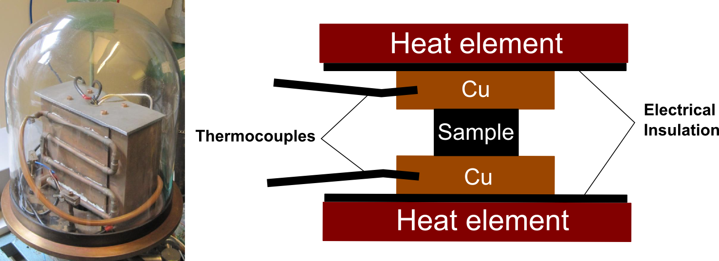
Figure 3: Equipment for measurement of the seebeck coefficient. The sample is placed between two copper blocks and thermocouples are attached to each block. The seebeck voltage is measured through the thermocouples while a constant temperature gradient in the region of 3 oC is forced over the sample. The apparatus is used at temperatures up to 500 oC.
Thermoelectric characterization of oxides requires the assessment of thermal and chemical equilibrium as a change in oxygen content could result in a substantial change in the charge carrier concentration and hence the thermoelectric transport properties. BATE has therefore also developed a separate apparatus for simultaneous measurements of the seebeck coefficient and electrical conductivity at temperatures of up to 1200 °C in controlled atmospheres. A Hall measurement setup from MMR-tech can also be used to measure the electrical conductivity and carrier concentration from 70 K to 730 K

Figure 4: High temperature equipment for simultaneous measurement of Seebeck coefficient and resistivity up to 1200 oC.
.jpg)
Figure 5: Seebeck voltage as function of temperature difference across the sample measured with the high temperature setup shown above. The Seebeck coefficient is determined from the slope.